Signal Power
Where P is the Signal Power in milliwatts typically
Channel Capacity
Where is the Bandwidth (Hz), is the signal power, is the noise power, and is the channel capacity in bits (bps).
Sometimes you will see this formula without specified, in which case and this is specified for each frequency
ADC Resolution:
Where is the number of voltage intervals and is the resolution of the ADC
ADC Voltage Resolution / Least Significant Bit:
Where is the () and M is as before. in most systems is referred to as the “noise floor” As noted, this tends to define your least significant bit voltage
Dynamic Range:
Where is the least significant bit as specified earlier
Effective Number of Bits (ENOB):
Where is a term that converts decibels to bits, and is the Quantisation Error In systems with lots of noise, not all of our voltages are “useful”, so we use ENOB to calculate how many bits are useful
Nyquist Frequency:
Where is the sampling frequency and where = the highest frequency in the system you are trying to record.
Convolution:
Where is the fourier transform of a function
Amplitude Modulation:
Where is the sample number, and is the total number of samples is the carrier frequency is the modulation amplitude is the carrier amplitude
It is also to note, you need to create samples per bit, where is the carrier frequency (see: Nyquist)
Frequency Modulation:
This can be filtered by mulitplying this all by a term
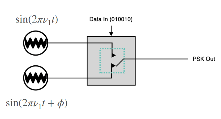
Binary Phase Shift Key (PSK)
IQ Modulation:
Where the green section is the and the red section is the Where:
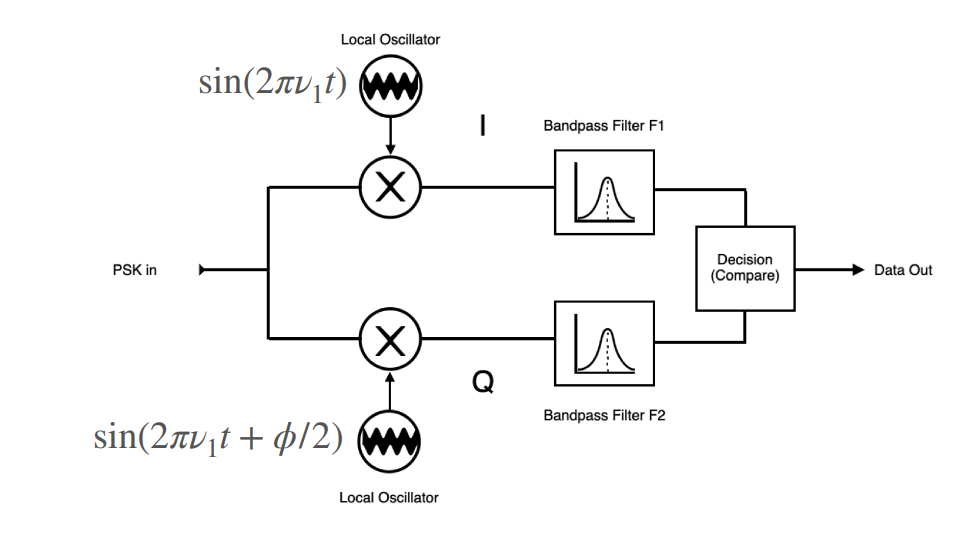
Demodulation :
In Phase: Multiply by Quadrature: Multiply by
Both of these will leave a constant x the arm, plus the other side which is frequency dependant, and therefore can be filtered out
Noise Power Distribution:
Where is the standard deviation of the system
Fading Formula:
For Just Fading:
Where is the transfer function for the enviroment
In general:
Where is the received signal
Rayleigh Fading:
Free Space Path Loss:
Where is the powers of the receiver and transmitter and is the directionality at both.
In cases where you don’t have directional receivers we use:
Filter Response:
Where is the order of the system, and is the cut off frequency
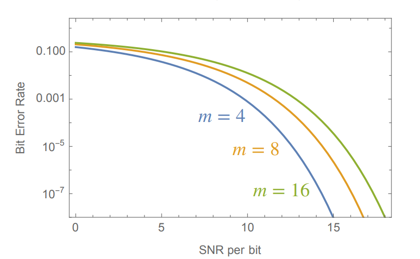
Bit Error Rate:
where
and is bandwidth, is baud rate, and is the bit depth
Impedance Mismatch:
Standing Wave Ratio:
Reflection:
Quality Factor:
General Knowledge:
Transmitter Structure:
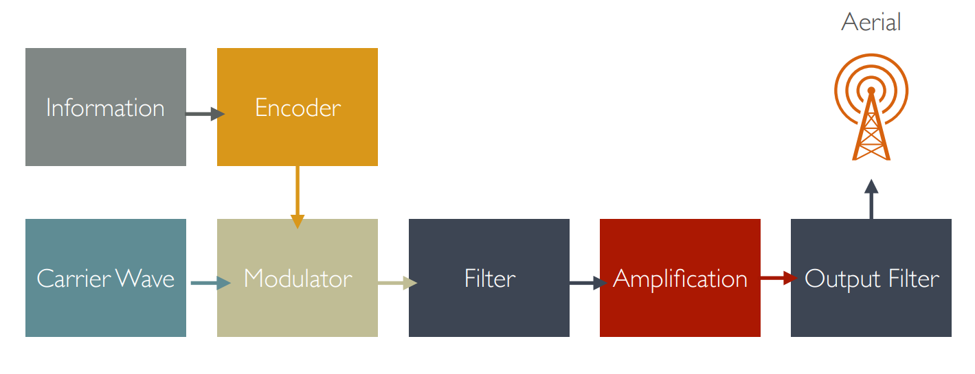
Encoder:
Takes data and encoders into a format suitable for transmission, typically with discrete high and discrete low voltages.
Carrier Wave:
These are created using oscillators, basic oscillators can be LC circuits, though for higher accuracy and higher frequency waves, we use crystals such as quartz. These crystals are used in Surface Acoustic Wave Devices (SAW) that generate physical waves upon an electrical stimulation
Modulator:
On off keying can be done using a transistor where:
- Collector : Carrier Wave
- Base : Digital Signal
- Emitter : Modulated Signal
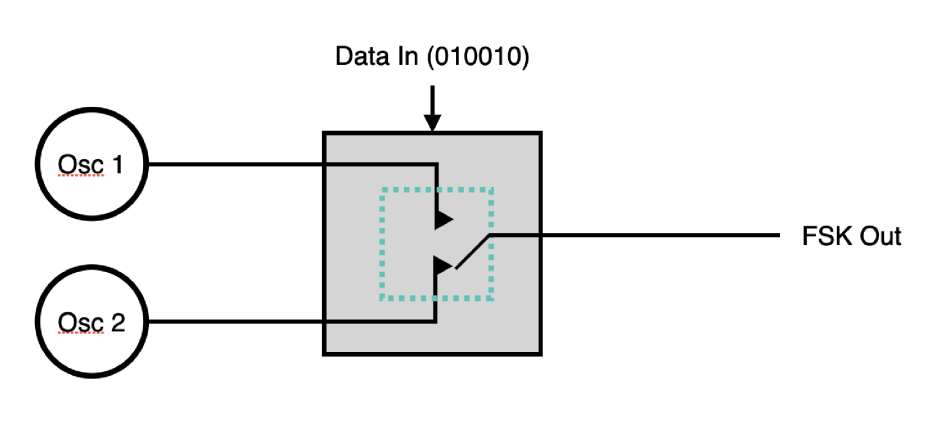
Other types of Keying/Modulation are Frequency Shift Keying (FSK) and Multi Level (i.e. 4 level) ASKs, which are used in lower noise systems
Filter:
Since we pay for all the bandwidth we use, it’s typically a good idea to filter less important frequencies so we don’t pay for useless bandwidth.
We can use LCR circuits and convolution for this:
Amplification:
This is where we boost the signal so as to for it able to be received by the other side, this does however introduce noise which is why we have:
Output Filter:
This filter is used to mitigate any noise added by the amplification
Data Throughput:
- Optical Fibre : >Pbps
- Ethernet Cat 5 : > 1 Gpbs
- SuperSpeed USB : 10 Gbps
- Serial : 100 kpbs
- 5g : 1 Gbps
- Wifi : 250Mbps
- Bluetooth : 1 Gbps
- Freesat : 50Mbps
Diagrams:
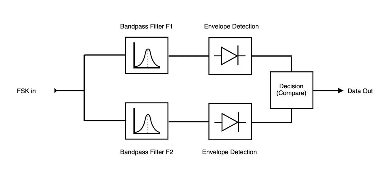
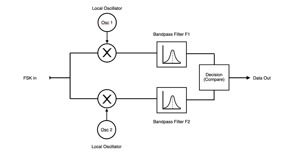
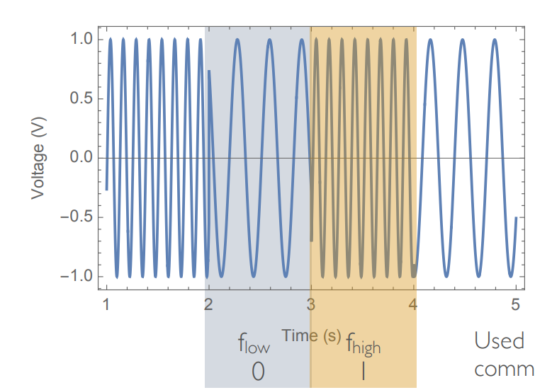
FSK:
Modulation:
Demodulation:
Async:
 Synchronous:
Signal:
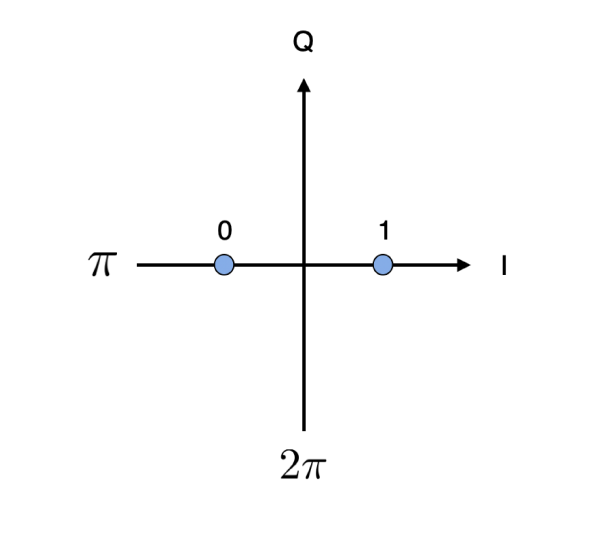
PSK:
Diagram:
Modulation:
Demodulation:
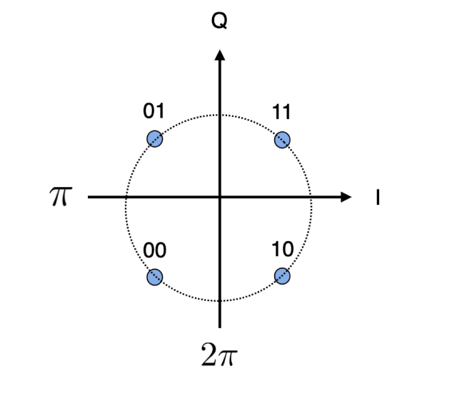
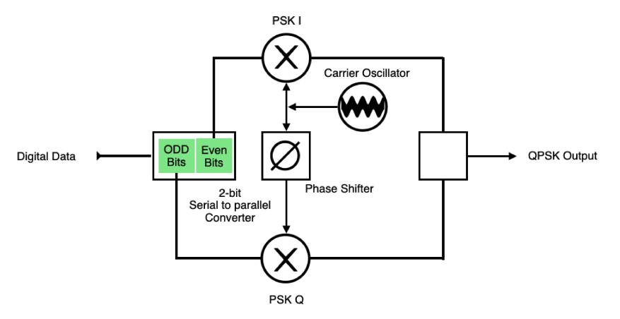
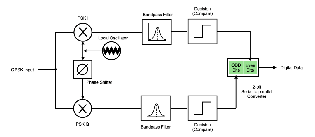
Quadrature Phase Shift Key (QPSK):
Diagram:
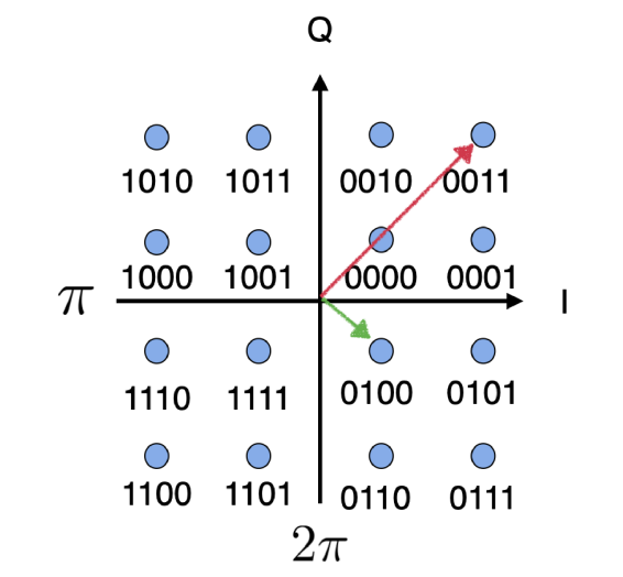
QPSK vs 8-QPSK
 or
or 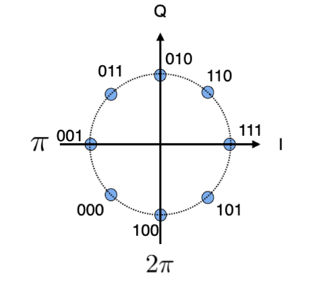
Modulation:
Demodulation:
Quadrature Amplitude Modulation (QAM):
Diagram
QAM-4:
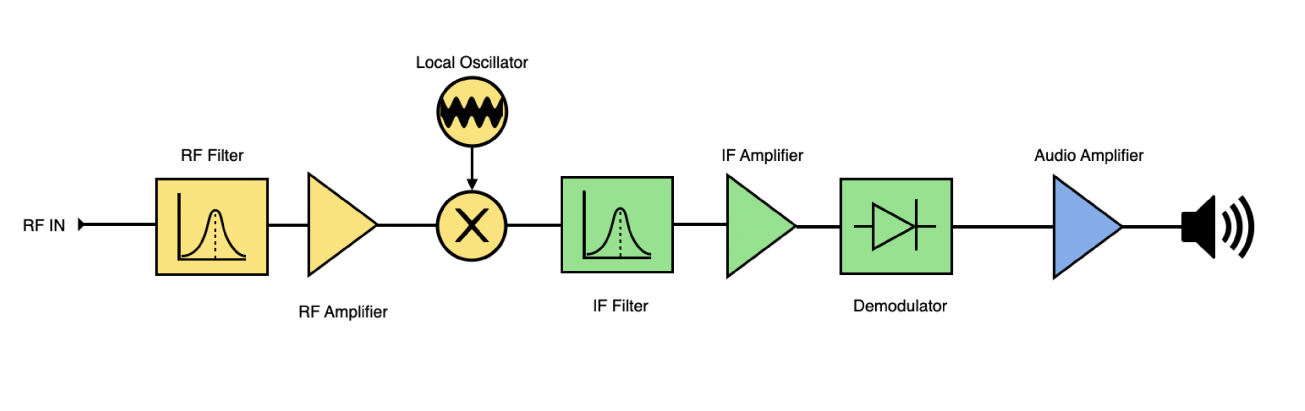
SuperHeterodyne Receivers: