Abstract:
A physical device that is used to store program code or data of a processor on either a temporary or a permanent basis, typically classified into two types:
- Volatile Memory
- Faster and less costly
- Used for temporary storage like caching and internal memory
-
- RAM
- Non-Volatile Memory
- No power is required to hold the data in memory
- Slower access speed, and more costly
- Used for long term storage
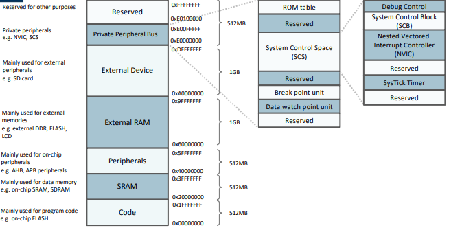
Most memory can dynamically and flexibly defined by the user, except some fixed memory addresses, such as the internal private peripheral bus.
General:
Memory is accessed by presenting the computer with an address from where data is read or written into.
A drawn example of a 8 bit wide memory structure that holds 8bits of data is as follows:
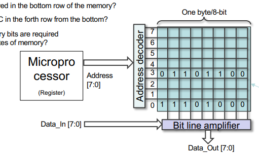
Memory addresses tend to start from the bottom up An address bus of 32 bits can be used to access locations of memory, but since each piece of memory for us stores a byte, we can say that it can be used to access bytes of memory
Memory Access in Depth:
The two following operations are as follows:
Write Data:
- Provide an address to the memory address bus
- A particular “word” is then selected by the address decoder and connected to our Bit Line Amplifier
- This may include breaking the memory down into columns and rows for larger memory
- The data gets presented to the Data_In ports of the microprocessor
- The bit line amplifier sets the bit lines to the desired values and then drives that data from itself to the memory cells.
Write Data:
- Provide an address to the memory address bus
- A particular “word” is then selected by the address decoder and connected to our Bit Line Amplifier
- This may include breaking the memory down into columns and rows for larger memory
- The selected data is connected to the bit line amplifier;
- The amplifier restores the signal to the proper voltage level, then outputs it to the Data_Out ports of the processor;
For an explanation of every section of the Memory Map:
Here
Program Image:
You can think of this almost as a start up routine for the microcontroller, It contains:
- Vector table
- Includes the starting addresses of exceptions (vectors) and the value of the main stack point (MSP);
- C start-up routine;
- Program code
- Application code and data;
- C library code
- Program codes for C library functions.
Here’s the program image for the ARM Cortex M0:
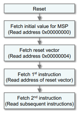 1st Instruction here is:
Branching to the starting of the programme execution address (reset handler)
2nd Instruction is executing the program.
1st Instruction here is:
Branching to the starting of the programme execution address (reset handler)
2nd Instruction is executing the program.
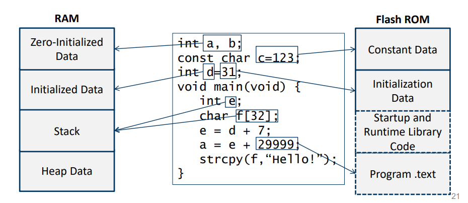
Memory Use By Program: