Abstract
It’s helpful in this way to think of cables as a filter with a particular capacitance and inductance depending on the material chosen for their construction.
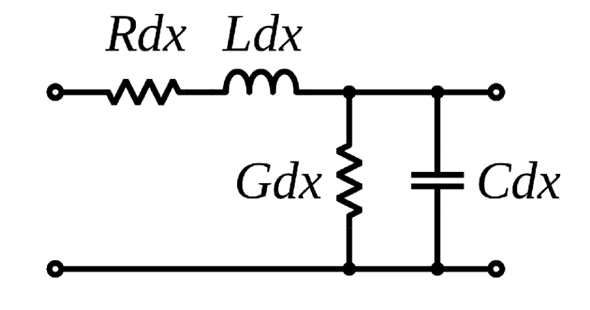 Where the inductance and capacitance both act to filter out frequencies. The diagram above helps us decide the Transfer Function of our Coaxial Cables for example
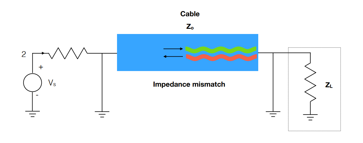
Interference and Reflection
Any mismatch in impedance can lead to interference at the boundaries between components, which can be very damaging for transmission of sound or signals:
Formulas:
Determining Cable Bandwidth
Shunt Capacitance
Where:
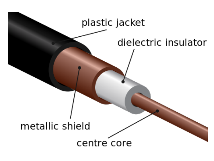
- C is the capacitance of the coaxial cable.
- is the length of the cable.
- is the permittivity of free space.
- is the relative permittivity of the dielectric material between the conductors.
- is the diameter of the outer conductor.
- is the diameter of the inner conductor.
Series Inductance
- L is the inductance of the cable
- is the permeability of free space.
- is the relative permeability of the dielectric material between the conductors.
Effective Impedance
Standing Wave Ratio
Reflection
Bandwidth of Cable
Where:
- represents the inner diameter of the outer conductor of the coaxial cable.
- represents the outer diameter of the inner conductor of the coaxial cable.
- is the Relative Permeability, a dimensionless measure of the circuits formation of magnetic fields within itself, simply, a measure of how much better or worse than a vacuum the material is at magnetizing itself
- is the Relative Permittivity, like before, but with electric fields
Speed of Transmission:
Where:
- is the Relative Permeability, a dimensionless measure of the circuits formation of magnetic fields within itself, simply, a measure of how much better or worse than a vacuum the material is at magnetizing itself
- is the Relative Permittivity, like before, but with electric fields
Diagram:
Transmission Modes in Cables:
- TE mode: Transverse Electric
- This has no electric field in the direction of propogation
- TM Mode: Transverse Magnetic
- No magnetic field in the direction of propogation
- TEM: Transverse ElectroMagnetic
- No electric or magnetic field in the direction of propogation
- Hybrid:
- Non-zero electric and magnetic fields in the direction of propogation
Having a ground line that surrounds the transmission line actually helps promoting TEM modes along the cable