Abstract:
A transmitter is a device that as the name suggest, transmits some form of signal.
The basic components of a transmitter are as follows:
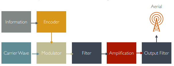
Breaking this down:
Encoder:
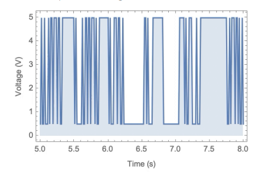
Information typically needs to be encoded in a way that is suitable for transmission, more methods will be discussed later, but for now lets assume the following binary encoded into discrete High (5V) and Low (0.5V):
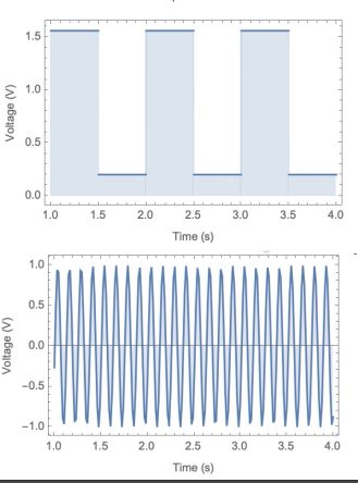
Carrier Wave:
The carrier wave can take many forms depending on the particular type of communications channel. Ex. For radio systems this is an Electromagnetic Wave with a certain frequency, we can use LC circuits, but crystals such as quartz tend to give more accurate timings. Continuing on crystals, Surface Acoustic Wave (SAW) devices use the generation of surface waves from well machined Piezo Electric materials to generate accurate waves.
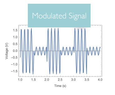
Modulators
This is the component that mixes the information with the carrier wave. Modulation tends to be achieved through a transistor.
The encoded signal is transmitted through the base, the carrier wave is passed in to the collector, and the wave comes out the emitter.
A large factor that affects us is the Additive White Gaussian Noise (AWGN) , Which also adds to Fading (Signal)
The time between each data point, is determined by the Baud Rate, in addition to this due to the Nyqusit Theroem we also know that we must sample at least twice , so we effectively upsample our data, so if our carrier wave is 4 times the time for a bit, we sample 8 times a bit. We can replicate modulation with
Amplitude Modulation
A common mode of modulation that is still used in tv remotes as well as NFC is Amplitude Shift Keying (ASK) , an example:
Further examples are Amplitude Modulated Signal (AM)
It’s also to be noted multiple different amplitudes can be used in ASK, however the limiting factor is the noise of the system
Frequency Modulation:
For this system, we vary our frequency between 0 and 1 bits like such:
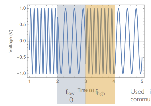 This is called Frequency Shift Keying (FSK)
This is used in bluetooth and is much less affected by background noise
This is called Frequency Shift Keying (FSK)
This is used in bluetooth and is much less affected by background noise
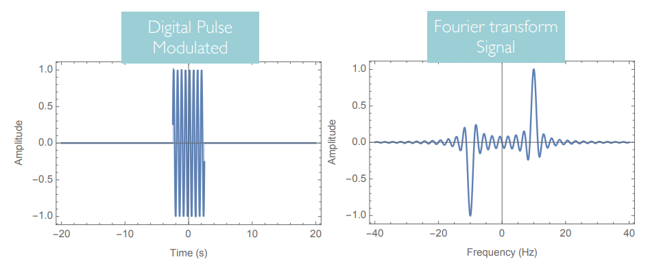
Filter
 Considering only positive frequencies:
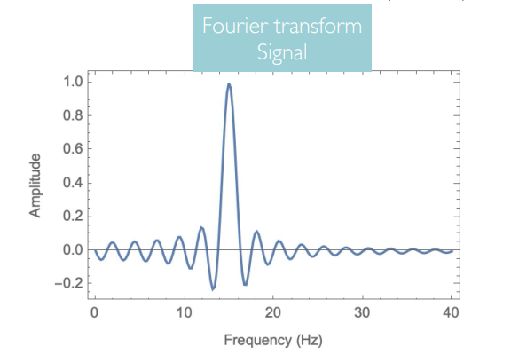 As we can see here, we are producing a very broad range of frequencies which in real systems would overlap onto other Spectral Bands and get us fines;
Therefore we use bandpass filters to limit the range of frequencies we create.
As we can see here, we are producing a very broad range of frequencies which in real systems would overlap onto other Spectral Bands and get us fines;
Therefore we use bandpass filters to limit the range of frequencies we create.
Notably however, bandpass filters dont have linear or straight cutoffs, rather they have a more curved profile.
Convolution can be applied here, where the output is actually:
which is the inverse Fourier transform of the product of fourier transforms of both constituent parts.
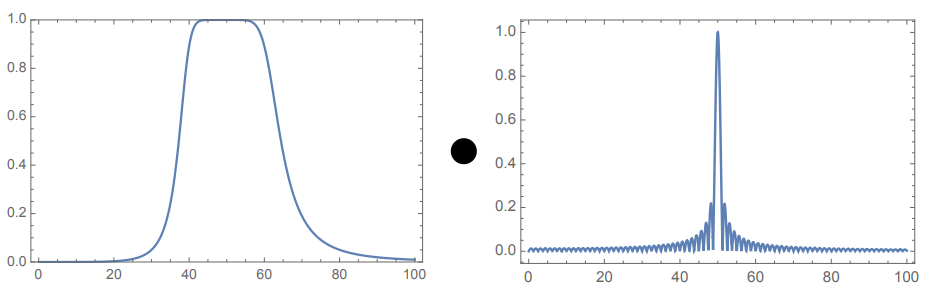 The bandpass in the example is a Butterworth Filter .
Amplification:
Amplification is typically done in multiple stages to avoid noise, however the core purpose is to boost the signal so it can be received on the other side
Output Filter:
This typically is a precaution taken to avoid the introduced noise from Amplification.