Abstract
A block diagram of a system is a graphical representation of the interconnections between the components of the system and the flow of signals. The diagram is composed of functional blocks which contain the mathematical operations of the components.
Ex:
Consider this system:
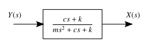
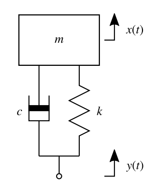 The equations of motion of this system are defined by:
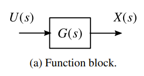
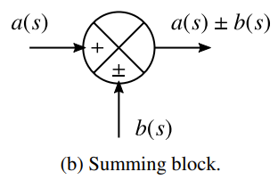
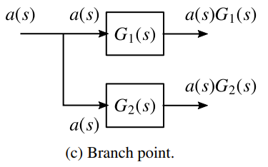
Basic Elements
Rules for Reduction
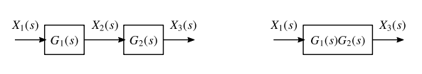
Rule 1: Cascaded Blocks
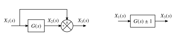
Rule 2: Summing Two Signals
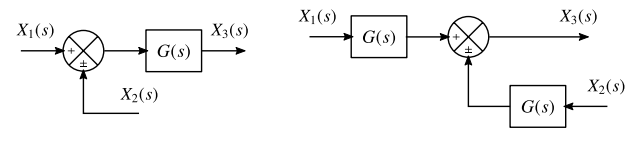
Rule 3: Moving a summing point back
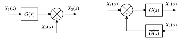
Rule 4: Moving a summing point forward
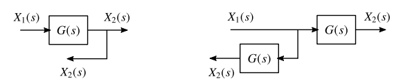
Rule 5: Moving a branch forward
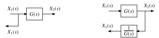
Rule 6: Moving a branch behind
Rule 7: Eliminating Feedback Loop
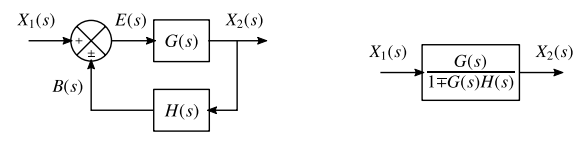 is known as the Error Signal and as the Feedback Signal
Worked Examples of Block Diagram Reduction
Ex 1:
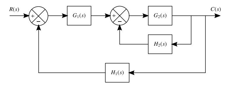
The second loop can be restated as , then following that we get: ( ) in a feedback loop with
This can be restated as a single block as:
or