First Order Systems Second Order Systems Transfer Function Types of Input Signal Block Diagrams Poles and Zeros of a Dynamic System Routh’s Stability Criterion Frequency Domain Analysis Nyquist Stability Theorem Point of Instability Analysis Bode Diagram Laplace Transform
Data Sheet
Standard System Responses
First Order Systems
A standard first order system has a differential equation:
This has a Laplace Transform Representation:
The step response of this system, assuming zero initial conditions is:
The time constant is defined as and the final output of the system is . The value of is defined in terms of by the following table.
| Time | |||||
|---|---|---|---|---|---|
| Output |
Second Order Systems
A standard second order system has a differential equation:
This has a Laplace Transform Representation:
The step response of this system, assuming zero initial conditions is:
Where and the final output of the system is . The relationship between the angular position of the poles, , damping factor, , and the percentage overshoot, , which occurs at time is shown by the following table.
| Damping Factor | ||||||
| Percentage Overshoot |
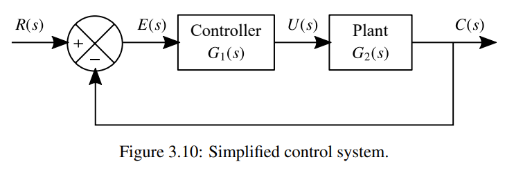
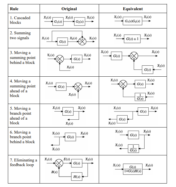
Block Diagrams
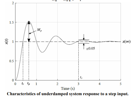
Characteristics of the Response of an Underdamped Second-Order System to a Step Input
The response of a second-order system to a step input can be characterised by four properties:
Where:
- is the undamped natural frequency of the system,
- is the damping ratio,
- is the steady-state value
- is the damped natural frequency, given by
Basic Controller Set Up
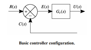
Error Transfer Function
Where: