Index: Electronic System Design 3, Perfect Opamps
Abstract:
This is the realistic model of an Op-Amp In general Op-Amps that are designed to be very effiecient at one thing, (i.e. current errors) are the least efficient for the opposite (or generally just other) concept (i.e. voltage errors)
Differences:
Perfect Opamp:
Imperfect Opamp:
- Current Flows in Inputs:
- Bias
- Offset
- Slow
- O/P has finite impedance (but reduced by feedback )
- Input Voltage Error
- Offset
- Common-Mode Rejection (CMRR)
- Power Supply Rejection
- Drift (Time/Temperature)
Measuring our imperfect op amps:
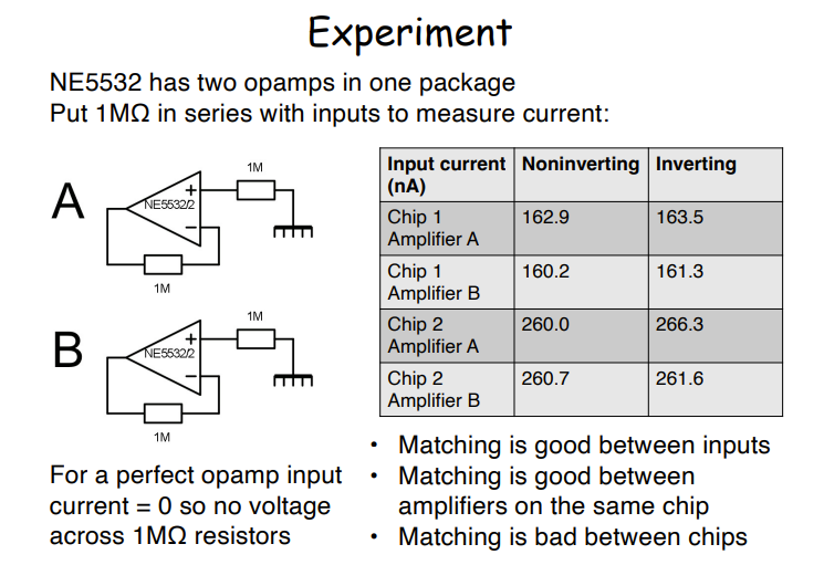 Now logically for our perfect op amps, all these values are 0, as Vin + should be 0 and by the Virtual Earth Principle (VEP) we should find Vin - should also be 0, and therefore with 0 voltage over the feedback resistor we should find 0 current, however as we see here, not only do we get current, but we in fact get slightly different current values on the inverting and non inverting input resistors.
How we can calculate these
- First we calculate the model for the PERFECT Opamp and then we add perfect current sources to represent our inaccuracies
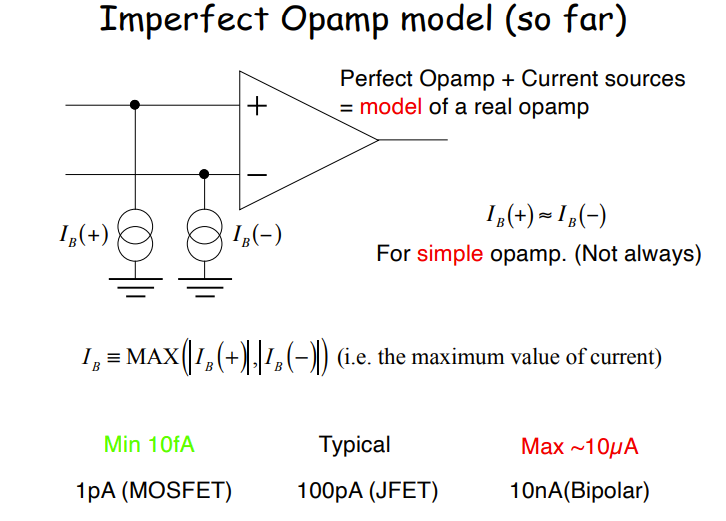 While we look at this and are tempted to say Bipolars are the worst of all 3 this tends to be only for current performance, as the opposite range is true for voltage performance.
The difference in current error between max and min error is literally a BILLION times
While we look at this and are tempted to say Bipolars are the worst of all 3 this tends to be only for current performance, as the opposite range is true for voltage performance.
The difference in current error between max and min error is literally a BILLION times
We specify a (sub)system
- Function (Gain of +10)
- External connections (source, voltage range, impedance)
- Performance (scale and offset error, bandwidth , power dissipation )
We make a naïve design:
- Full design with an op amp (pick cheap first), and component values.